God of All Monitors Water Cooled - Asus PG27UQ
- Theodore Tzanetos
- Apr 2, 2020
- 5 min read
Updated: Jun 11, 2020
This project all started with my PC enthusiast hobby, centered around building a high performance PC, optimizing for silence, and managing the resulting heat. My PC was originally built in 2016, and was at the time a bleeding edge PC, sporting an Intel i7 6700K CPU, NVIDIA GTX Titan X GPU and the associated top-of-the-line support hardware. It was my first water-cooling experience, and I succeeded in completing my PETG hardline, hand-bent, single loop system.
Fast forward to 2018 when Asus first announces the PG27UQ and I was sold, it was the perfect pairing for my workstation PC. It was as LinusTechTips called it (https://www.youtube.com/watch?v=u-7IXNLeY3c) the "God of Monitors". Ill leave the lengthy technical breakdowns to:
AND
In summary this pinnacle of engineering sports:
4k Native Resolution
Up to 144Hz Refresh Rate, with OC enabled
G-Sync Ultimate (remember this)
Quantum-dot, IPS Dsplay Panel
HDR1000
There are two major flies in the ointment however...
1) As guru3D explains, you can't enable all the bells and whistles at once due to throughput limitations in the DisplayPort version used by this monitor. You can trade off refresh rates or select chroma subsampling for example.
2) An always-on fan is needed to keep the G-Sync Ultimate FPGA always on
The chroma subsampling was not an issue, I accepted a lower refresh rate of 98Hz. However, the droning of an always-on fan which is 12 inches from my face, inside of a $1k+ monitor was unacceptable, which is why I decided it needed to be watercooled!
PCPER.COM's teardown photos gave me the initial hopes that the thing could be watercooled, but I knew no one would make a special waterblock for it, so I had to disassemble the monitor and take some measurements.
Before we begin, the actions described below will likely void your warranty. There is a high chance of you damaging your perfectly functional top-of-the-line monitor. Also, as with any electronics device there is a chance of personal injury. Please read the disclaimer on the homepage.
Assumptions
While expensive, there is no magic inside this monitor. Branding aside, its an embedded system, with an FPGA used for handling the complex timing challenges inherent to variable refresh rate technology. All credit to NVIDIA/ASUS for making a beautiful technology, even with acoustic issues, but I want to dispel any fear in the modding community about approaching cutting-edge technology. That FPGA produces a lot of heat, so ASUS decided that they would use a small heatsink, and a loud blower to dissipate/expel the heat away, keeping the FPGA and its surrounding components safe
I could find a compatible heatsink (more of a Hail Marry/Luck). Like all chips on the market, dimensions are standardized. The Altera Arria 10 FPGA is a COTS part (albeit an expensive one), and I was hoping that NVIDIA subscribed to some manufacturer's recommended heatsink setup/dimensions.
The only reason the fan was needed was for FPGA cooling.
Disassembly
A spudger needs to be used to pry open the clam shell of the monitor casing. Care must be taken to not rip off any of the ribbon cables, high bandwidth interfaces, or other small-pin harnesses going to the monitor's motherboard. In total you need to disconnect 10 items before you can extract the motherboard, all annotated below. Note item (8) is an EMI/EMC shielding strap which needs to be carefully peeled away. WARNING there is a large connector (4) on the underside of the motherboard housing, when lifting the motherboard plate up off the back of the monitor, you must carefully release the ribbon first. Item (10) is the LED backarray and (9) is the harness for the side panel buttons.


The first image below shows the extracted motherboard showing. The second image shows the backside of the motherboard.


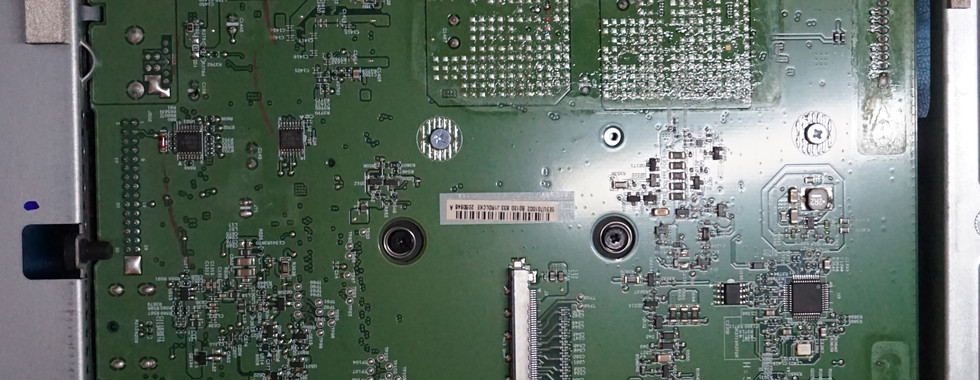


You must pull back some aluminum retaining tabs on the backside of the aluminum housing to pull the motherboard (with the G-SYNC Module/ FPGA daughter-card), out of the housing. Image 3 shows the bare motherboard, with the FPGA card still attached, and the offending blower style fan along with its black plastic ductwork.
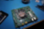
Removing the blower fan, duct, and heatsink will reveal the beautiful FPGA card, shown in image 4.
Waterblock Mounting
Now came the lucky part. After measuring the hole spacing to be a ~46.875mm square, i found the following heatsink on Amazon.(affiliate link)


This heatsink has slots on all 4 sides, which allows for a range of hole spacing. Some modification was necessary, since the screws provided needed to be trimmed, as shown in the side view of image 3. You can also see in image 3, that because of the 45degree shift in the heatsink mounting-hole-to-copper-plate orientation, that the entire square heatsink block is rotated 45degrees relative to the FPGA die. While not ideal (nothing in this project is) the loss in thermal conductivity was irrelevant to the final results. You will also notice the tubing connectors shooting off the waterblock. Note that the connectors shown (with the 90degree fittings, etc) differs from the final configuration photos below since the fit subsequenct fit checks necessitated a change to the fitting choices, specifically to the fitting protruding out of the circular cutout.
I was EXTREMELY lucky that the aluminum housing had cutouts in approximately the area around the waterblock, which proved to be useful for routing the fluid tubing.
You can see in the below images the final routing needed. Image 1 shows the original routing path, and image 2 shows the final path. The central circular hole in the aluminum frame aligns with the VESA mounting holes. I opted instead to route the tubing along the side of the motherboard where there was plenty of room, shown in image 2-3.
My SC2, COD, and IT buddy Wilson thankfully argued me into installing some means of thermal monitoring on the system, which you can see image 4 below. I repurposed a 10K-ohm Negative-Temperature-Coefficient Thermistor and used Arctic Silver Thermal Adhesive to bond the TC to the side of the waterblock's copper plate.
Images 5 shows the capped-off wires from the 2x system fans, in the event that I either needed to
1) Revert back to air cooling
2) Install a spoofing circuit, to trick the monitor into thinking that a fan was spinning. Thankfully this was not necessary, but it always helps to try and think ahead for gotchas.


Final Setup and Thermal Results
The images below show the as-assembled final result
Image 1: View of both loop ports, showing outlet, inlet, the NTC thermal prove wires. Note the VESA interface is still functional
Image 2: Close up view of the modifications needed to access the watercooling fittings. A Dremel was used to cutout the access holes in the plastic back panel
Image 3: EKWB Quick Disconnects
Image 4: Quick and dirty rad/pump setup underneath my desk. Excuse the mess, but the best part is that no fans are needed on the radiator to keep the FPGA below 38degC! I also wanted to ensure that I could never turn on the monitor with the waterpump not on, so i connected the 120VAC power of the monitor to relay-controlled power strip, which was slaved to the pump's PWM controller.
Links to the parts:


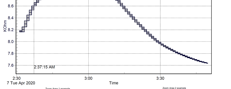
For those interested in the thermal time constants of the loop, I did extermiment with fans on the radiator, and recorded the thermistor resistance using my Fluke 289 connected to desktop via FlukeView.

Please feel free to reach out with questions!
For comments, questions, etc...